Most of the circuits are for applications in millimeter wave wireless LAN.
The following electronic papers at this web site are in journal publications and therefore have copyrights attached to them. Personal use of this material is permitted. However, permission to reprint/republish this material for advertising or promotional purposes or for creating new collective works for resale or redistribution to servers or lists, or to reuse any copyrighted component of this work in other works must be obtained from the the appropriate publisher.
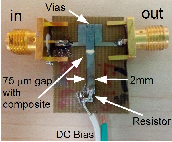
For more information see:
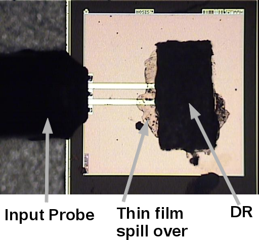
For more information see:
A.P. Freundorfer, P.V. Bijumon, and M. Sayer
Department of
Electrical and Computer Engineering
Queen's University
Kingston,
Ontario, Canada K7L 3N6
freund@queensu.ca
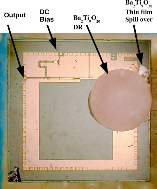
Simulation:Agilent ADS and Ansoft HFSS
Layout
tools: ADS and Cadence
Fab: Nortel MESFET
Technical Support:
Queen's
Funding: NSERC
For more information see:
P. V. Bijumon, Y. M. M. Antar, A. P. Freundorfer, and M. Sayer
Department of
Electrical and Computer Engineering
Queen's University
Kingston,
Ontario, Canada K7L 3N6
freund@queensu.ca
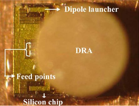
Simulation: Ansoft HFSS
Layout
tools: ADS and Cadence
Fab: IBM SiGe
Technical Support:
Queen's and Royal Military College
Funding: NSERC
For more information see:
B.M. Frank1, M. J. Keller2, H.F. Hammad1, P. R. Shearing2, A.P Freundorfer1, Y.M.M Antar2
1 Department of Electrical and Computer Engineering,
Queen's University
2 Department of Electrical and Computer Engineering,
Royal Military College of Canada
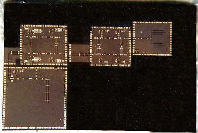 Receiver chip with 27 GHz DRO, 30 GHz antenna, 30 GHz amplifier and down convert mixer.
Simulation: HP/eesof Libra series IV (primary) and Zeland
IE3D (secondary)
Layout tools: HP/eesof Libra series IV
(secondary), Zeland IE3D (secondary) and Cadence (primary)
Fab:
Nortel 0.8 micron Sagfet (through Canadian Microelectronics
Corporation) and Nortel
Technical Support: CRC, Nortel
Technologies and COM DEV
Funding: Nortel, NSERC and CITO
For more information see:
B.M. Frank, M.J. Keller, H.F. Hammad, P.R. Shearing, A.P. Freundorfer and Y.M.M. Antar, "An Integrated Receiver for Wireless Applications," Symposium on Antenna Technology and Applied Electromagnetics, ANTEM'98, Ottawa, Canada, Aug. 1998, pp. 95-98.
P. R. Shearing, A.P. Freundorfer and Y.M. Antar
Department of
Electrical and Computer Engineering
Royal Military College of
Canada
Kingston, Ontario, CANADA
freund@queensu.ca
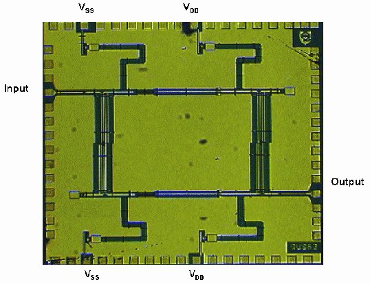
Chip Photograph CG Balanced Amplifier
Simulation: HP/eesof Libra series IV (primary) and Zeland
IE3D (secondary)
Layout tools: HP/eesof Libra series IV
(secondary), Zeland IE3D (secondary) and Cadence (primary)
Fab:
Nortel 0.8 micron Sagfet (through Canadian Microelectronics
Corporation) and Nortel
Technical Support: CRC, Nortel
Technologies and COM DEV
Funding: NSERC and CITO
For more information see:
P. Shearing, A.P. Freundorfer and Y. Antar, "A Coplanar Ka-Band Common-Gate Amplifier in 0.8mm GaAs MESFET," Symposium on Antenna Technology and Applied Electromagnetics, ANTEM'98, Ottawa, Canada, Aug. 1998, pp. 61-64.
P. Shearing, "Ka-Band Balance MESFET Amplifier," Royal Military College, M.Sc. 1997.
B.M.Frank, A.P. Freundorfer and Y.M. Antar
Department of
Electrical and Computer Engineering
Royal Military College of
Canada
Kingston, Ontario, CANADA
freund@queensu.ca
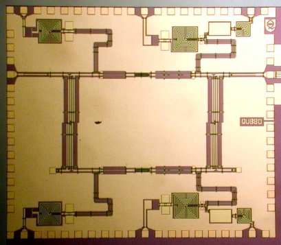
Chip Photograph CG Balanced Mixer
Simulation: HP/eesof Libra series IV (primary) and Zeland
IE3D (secondary)
Layout tools: HP/eesof Libra series IV
(secondary), Zeland IE3D (secondary) and Cadence (primary)
Fab:
Nortel 0.8 micron SAGFET (through Canadian Microelectronics
Corporation) and Nortel
Technical Support: Nortel
Technologies
Funding: NSERC and CITO
For more information see:
B.M. Frank, A.P. Freundorfer, Y.M.M. Antar, 1999, "A Novel Common Gate Mixer for Wireless Applications," European Microwave Conference, GAAS'99, Munich, Session G-TuF5.
B.M. Frank, A.P. Freundorfer and Y.M.M. Antar, "A Novel Common Gate Mixer for Wireless Applications," IEEE Trans. on Microwave Theory and Techneques, Vol. 50, No. 5, May 2002, pp 1433-1435.
B. Frank, " A Novel Common Gate Mixer for Wireless Applications,” Queen's University, M.Sc. 1999.
I. Hilborn, A. P. Freundorfer, J. Show, and M. G. Keller
Department of
Electrical and Computer Engineering
Royal Military College of
Canada
Kingston, Ontario, CANADA
freund@queensu.ca
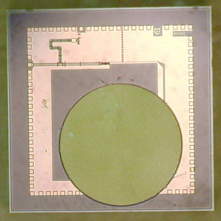
Chip Photograph of DRO
Simulation: HP/eesof Libra series IV (primary) and Zeland
IE3D (secondary)
Layout tools: HP/eesof Libra series IV
(secondary), Zeland IE3D (secondary) and Cadence (primary)
Fab:
Nortel 0.8 micron Sagfet (through Canadian Microelectronics
Corporation) and Nortel
Technical Support: Nortel
Technologies and COM DEV
Funding: NSERC and CITO
For more information see:
A.P. Freundorfer, Y.Jamani and C. Falt*
Department of
Electrical and Computer Engineering
Queen’s
University
Kingston, Ontario, Canada K7L
3N6
freund@queensu.ca
*Nortel
Advanced Technology Laboratory
PO Box 3511, Station
C
Ottawa, Ontario, Canada K1Y 4H7
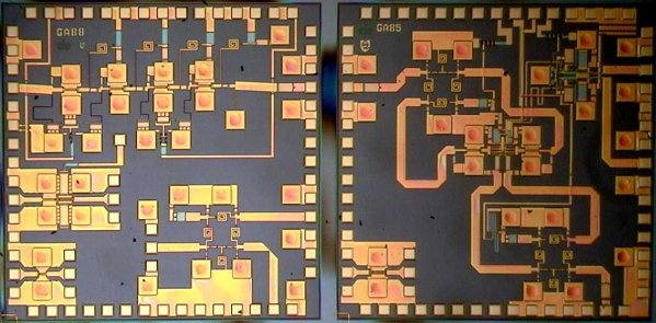
Receiver chip layout.
Simulation: Hspice, HP/eesof Libra series IV and Zeland
IE3D
Layout tools: HP/eesof Libra series IV (secondary),
Zeland IE3D (secondary) and Cadence (primary)
Fab: Nortel
HBT
Technical Support: CRC and Nortel Technologies
Funding:
NSERC and Nortel Technologies
For more information see:
A.P. Freundorfer and Y. Jamani, 1997, "A Ka-band GaInP/GaAs HBT Receiver," IEEE Antennas and Prop. Soc. Int. Symp./ 1997 North American Radio Sci. Meeting, 1997 IEEE APS Int. Symp/ URSI meeting, July, Montreal, Vol. 1, pp. 582-585.
A.P. Freundorfer, Y. Jamani and C. Falt, "A Ka-band GaInP/GaAs HBT Four-stage LNA," IEEE MTT-S 1996 International Microwave Symposium, San Francisco, June 16-21, 1996, paper TU1A-4.
A.P. Freundorfer and Y. Jamani, 1997, "A Ka-band GaInP/GaAs HBT Double Balanced Downconvert Mixer using Lumped Elements," IEEE Antennas and Prop. Soc. Int. Symp./ 1997 North American Radio Sci. Meeting, 1997 IEEE APS Int. Symp/ URSI meeting, July, Montreal, Vol. 1, pp. 578-581.
A.P. Freundorfer and Y. Jamani
Department of Electrical and
Computer Engineering
Queen’s University
Kingston,
Ontario, Canada K7L 3N6
freund@queensu.ca
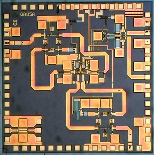
Simulation: Hspice, HP/eesof Libra series IV and Zeland
IE3D
Layout tools: HP/eesof Libra series IV (secondary),
Zeland IE3D (secondary) and Cadence (primary)
Fab: Nortel
HBT
Technical Support: CRC and Nortel Technologies
Funding:
NSERC and Nortel Technologies
For more information see:
A.P. Freundorfer and Y. Jamani, 1997, "A Ka-band GaInP/GaAs HBT Double Balanced Downconvert Mixer using Lumped Elements," IEEE Antennas and Prop. Soc. Int. Symp./ 1997 North American Radio Sci. Meeting, 1997 IEEE APS Int. Symp/ URSI meeting, July, Montreal, Vol. 1, pp. 578-581.
A.P. Freundorfer, Y. Jamani and C. Falt*
Department of
Electrical and Computer Engineering
Queen’s
University
Kingston, Ontario, Canada K7L
3N6
freund@queensu.ca
*Nortel
Advanced Technology Laboratory
PO Box 3511, Station
C
Ottawa, Ontario, Canada K1Y 4H7

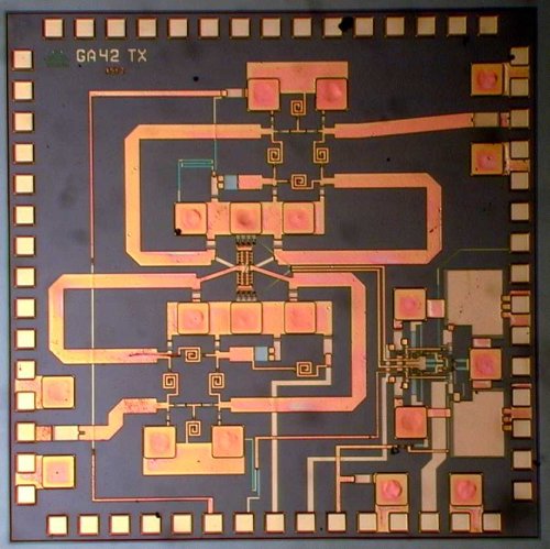
Layout
of four stage Ka-band LNA
Simulation: HP/eesof Libra series IV (secondary) and Zeland
IE3D (primary)
Layout tools: HP/eesof Libra series IV
(secondary), Zeland IE3D (secondary) and Cadence (primary)
Fab:
Nortel HBT
Technical Support: CRC and Nortel
Technologies
Funding: NSERC and Nortel Technologies
For more information see:
A.P. Freundorfer, Y. Jamani and C. Falt, "A Ka-band GaInP/GaAs HBT Four-stage LNA," IEEE MTT-S 1996 International Microwave Symposium, San Francisco, June 16-21, 1996, paper TU1A-4.
A.P. Freundorfer and Y. Jamani, 1997, "A Ka-band GaInP/GaAs HBT Receiver," IEEE Antennas and Prop. Soc. Int. Symp./ 1997 North American Radio Sci. Meeting, 1997 IEEE APS Int. Symp/ URSI meeting, July, Montreal, Vol. 1, pp. 582-585.
A.P. Freundorfer and C. Falt*
Department of
Electrical and Computer Engineering
Queen’s
University
Kingston, Ontario, Canada K7L
3N6
freund@queensu.ca
*Nortel
Advanced Technology Laboratory
PO Box 3511, Station
C
Ottawa, Ontario, Canada K1Y 4H7
Ka-band double balanced mixer with lumped element balun
Simulation: Hspice (primary) HP/eesof Libra series IV
(secondary) and Zeland IE3D (secondary)
Layout tools:
HP/eesof Libra series IV (secondary), Zeland IE3D (secondary) and
Cadence (primary)
Fab: Nortel HBT
Technical Support:
CRC and Nortel Technologies
Funding: NSERC and Nortel
Technologies
For more information see:
A.P. Freundorfer and C. Falt, "A Ka-band GaInP/GaAs HBT Double Balanced Upconvert Mixer using Lumped Element Balun," IEEE MTT-S 1996 International Microwave Symposium, San Francisco, June 16-21, 1996, paper OF-2-39.
Yi Sun and A.P. Freundorfer
Department of Electrical and
Computer Engineering
Queen's University
Kingston, Ontario,
Canada K7L 3N6
freund@queensu.ca
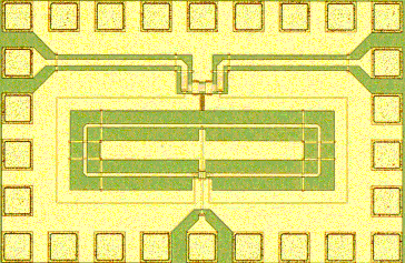
Simulation: ADS momentum and Zeland IE3D
Layout
tools: ADS (secondary), Zeland IE3D (secondary) and Cadence
(primary)
Fab: Nortel HBT
Technical Support:
Nortel Networks
Funding: NSERC and Nortel Networks
For more information see:
Yi Sun and A.P. Freundorfer, "Broadband Folded Wilkinson Power Combiner/Splitter," IEEE Microwave and Wireless Components Letters, Accepted, 2003.
K.W. Hamed, A.P. Freundorfer, Y.M.M. Antar
Department of
Electrical and Computer Engineering
Queen's University
Kingston,
Ontario, Canada K7L 3N6
freund@queensu.ca
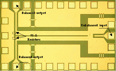
Simulation: ADS momentum and Zeland IE3D
Layout
tools: ADS (secondary), Zeland IE3D (secondary) and Cadence
(primary)
Fab: Nortel HBT
Technical Support:
Nortel Networks
Funding: NSERC and Nortel Networks
For more information see:
.W. Hamed, A.P. Freundorfer, Y.M.M. Antar, "A novel 15 to 45 GHz monolithic passive balun for MMICs applications," Microwave Symposium Digest, 2003 IEEE MTT-S International , Volume: 1 , 8-13 June 2003, pp. 31 -34 vol.1.
Yi Sun, A.P. Freundorfer and D. Sawatzky
Department of
Electrical and Computer Engineering
Queen's University
Kingston,
Ontario, Canada K7L 3N6
freund@queensu.ca
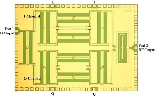
Simulation: ADS momentum and Zeland IE3D
Layout
tools: ADS (secondary), Zeland IE3D (secondary) and Cadence
(primary)
Fab: Nortel HBT
Technical Support:
Nortel Networks
Funding: NSERC and Nortel Networks
For more information see:
Yi Sun, A.P. Freundorfer and D. Sawatzky, "A QPSK DIRECT DIGITAL MODULATOR IN GaAs HBT at 28 GHz," Conference on Electrical and Computer Engineering, CCECE 2005, May 1-4, 2005, Saskatoon, Saskatchewan Canada, paper 1568953255.
Yi Sun, and A.P. Freundorfer
Department of
Electrical and Computer Engineering
Queen's University
Kingston,
Ontario, Canada K7L 3N6
freund@queensu.ca
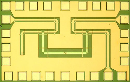
Simulation: ADS momentum and Zeland IE3D
Layout
tools: ADS (secondary), Zeland IE3D (secondary) and Cadence
(primary)
Fab: Nortel HBT
Technical Support:
Nortel Networks
Funding: NSERC and Nortel Networks
For more information see:
Yi Sun and A. P. Freundorfer, "A new overlay coupler for direct digital modulator in GaAs HBT," IEEE Transactions on Microwave Theory and Techniques,Vol. 52, No. 8 , Aug. 2004, pp. 1830 − 1835.
K.W. Hamed, A.P. Freundorfer, Y.M.M. Antar
Department of
Electrical and Computer Engineering
Queen's University
Kingston,
Ontario, Canada K7L 3N6
freund@queensu.ca
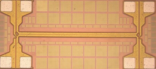
Simulation: Ansoft HFSS and Zeland IE3D
Layout
tools: ADS (secondary), Zeland IE3D (secondary) and Cadence
(primary)
Fab: IBM SiGe HBT
Technical Support:
Queen's University
Funding: NSERC
For more information see:
K.W. Hamed, A.P. Freundorfer, Y.M.M. Antar, "A Novel 20 to 40 GHz Monolithic Passive Differential Coupler for MMICs Applications ," 2005 IEEE MTT-S International Microwave Symposium Digest, Long Beach, USA, June 12-17, paper WE4E-3.
K.W. Hamed, A.P. Freundorfer, Y.M.M. Antar, Peter Frank, and Dave Sawatzky
Department of
Electrical and Computer Engineering
Queen's University
Kingston,
Ontario, Canada K7L 3N6
freund@queensu.ca
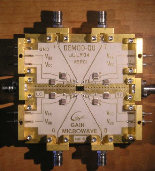
Simulation: ADS and Zeland IE3D
Layout
tools: ADS (secondary), Zeland IE3D (secondary) and Cadence
(primary)
Fab: Nortel GaAs
Technical Support:
Gain Microwave
Funding: NSERC
For more information see:
K.W. Hamed, A.P. Freundorfer, and Y.M.M. Antar
Department of
Electrical and Computer Engineering
Queen's University
Kingston,
Ontario, Canada K7L 3N6
freund@queensu.ca
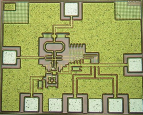
Simulation: ADS and Zeland IE3D
Layout
tools: ADS and Cadence
Fab: IBM SiGe
Technical Support:
Queen's
Funding: NSERC
For more information see:
Podilchak Symon, Frank Brian, Freundorfer Al, and Antar Yahia
Department of
Electrical and Computer Engineering
Queen's University
Kingston,
Ontario, Canada K7L 3N6
freund@queensu.ca
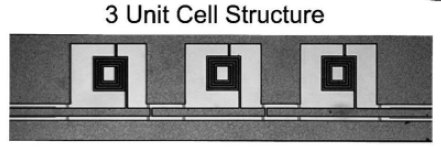
Simulation: Ansoft HFSS
Layout
tools: ADS and Cadence
Fab: IBM SiGe
Technical Support:
Queen's and Royal Military College
Funding: NSERC
For more information see:
Podilchak Symon, Frank Brian, Freundorfer Al, and Antar Yahia
Department of
Electrical and Computer Engineering
Queen's University
Kingston,
Ontario, Canada K7L 3N6
freund@queensu.ca
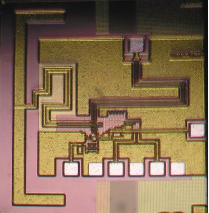
Simulation:Agilent ADS and Ansoft HFSS
Layout
tools: ADS and Cadence
Fab: IBM SiGe
Technical Support:
Queen's
Funding: NSERC
For more information see: